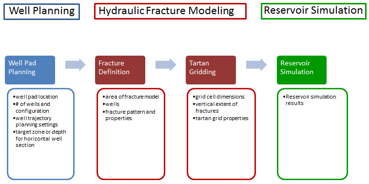
Steps in hydraulic fracture modeling
Tight rocks have increasingly become a major target for hydrocarbon exploration and production. Especially in North America, huge quantities of gas are contained in thick shale layers. Shale layers have low permeability and up to a decade ago economic production was not feasible. With technical developments like horizontal drilling and hydraulic fracturing, however, economic production from such reservoirs is now feasible.
Hydraulic fractures greatly enlarge the area around the well from which gas can be produced, although the effect is still limited to an area close to the well. This means that, to cover the entire reservoir, many horizontal wells need to be drilled, in most cases from a well pad set-up.
Hydraulic fracture modeling click to enlarge
In the hydraulic fracture modeling workflow, you create a fracture definition with fractures at specified locations along selected wells. Based on this model, you generate a tartan grid with small grid cells in the fractured areas allowing for detailed and accurate (dynamic) modeling and analysis, and coarser grid cells in between the fracture areas.
Steps
| Step | Description | See |
|---|---|---|
|
Create a fracture definition |
Define a fracture model that describes the hydraulic fracture modeling area, the wells involved, and the hydraulic fracture parameters:
|
Defining fractures |
| Define the perforations |
Set the type and size of the perforations that are specified in the grid fracture definition. |
Perforations at fractures |
| Create the tartan grid |
Create the tartan grid, straight lines of varying widths and distances, crossing at right angles. The tartan grid uses the fracture model as input and creates a tartan grid based on your specifications for grid cell size and grid cell size increase perpendicular to and along the wellbores and fractures. If the tartan grid is based on an existing 3D geological grid, you can map the properties of that geological grid to the tartan grid. |
Creating tartan grids |
| Map properties to the tartan grid | Map properties that you need for dynamic reservoir simulation modeling onto a tartan grid. You also specify if and how permeability of hydraulic and natural fractures is treated in dynamic simulation modeling. | Creating tartan grid properties |
| Create a simulation case |
Create a simulation case from the tartan grid and its properties for a selected dynamic reservoir simulator. |